AG09 COMMUNITY INFILTRATION SYSTEMS
Rainwater retention and infiltration elements located in community spaces.
Aim
Incorporate retaining and infiltrating rainwater elements in new or renovated residential areas or public spaces.
Why?
To mitigate the effects of climate change through design, moderating the rise in the temperature of the planet and the waste of energy and water resources.
They bring the following benefits:
– Improve environmental comfort regulating temperature and humidity. Reduction of the heat island effect due to the evaporation of water accumulated in the subsoil.
– Reduce flooding due to torrential rains.
– Reduce volumes of runoff and peak flows that end up in the network of collectors and the treatment plant to avoid overloading the sanitation infrastructure.
-Integrate rainwater treatment into the urban landscape.
-Protect water quality by reducing the effects of diffuse pollution.
-Improve the health of urban vegetation.
-They generate social benefits by creating attractive meeting and leisure spaces.
Cómo?
This involves transforming the current rainwater collection, which seeks the quick evacuation of urban runoff that is based on a system of impermeable surfaces and gutters connected to the sewers, into a system that retains and infiltrates the water from urban runoff using a set of nature-based elements that, working together, manage to infiltrate significant volumes of water into the subsoil.
In addition to the elements and techniques developed in AG06, there are two other structures which, due to their larger dimensions, are ideal for community spaces in residential areas, industrial or technological, educational or health areas, leisure and tourism complexes, parks and green areas.
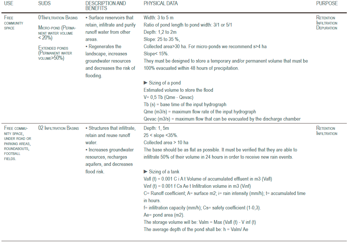
01 RETENTION PONDS
Water retention and storage area for infiltration, made up of artificial ponds with permanent layers of water and vegetation, both aerial and aquatic.
02 INFILTRATION TANKS
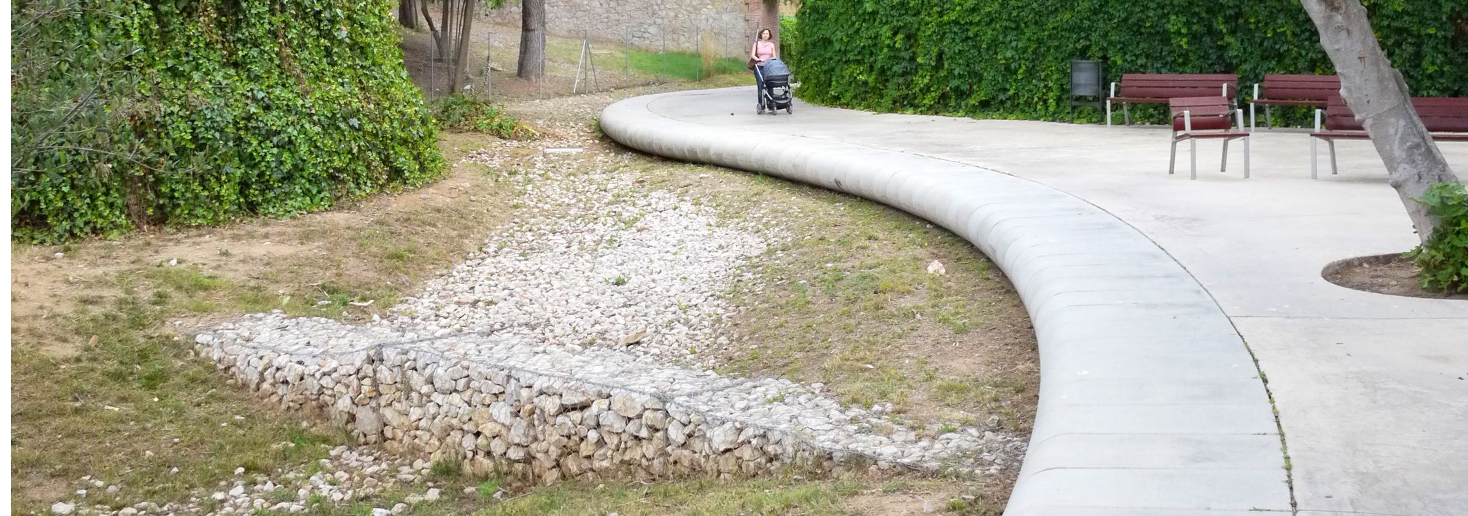
These are shallow, closed, irregularly shaped depressions or reservoirs in permeable soils designed to temporarily store, purify, and gradually infiltrate rainfall runoff from nearby impermeable surfaces.
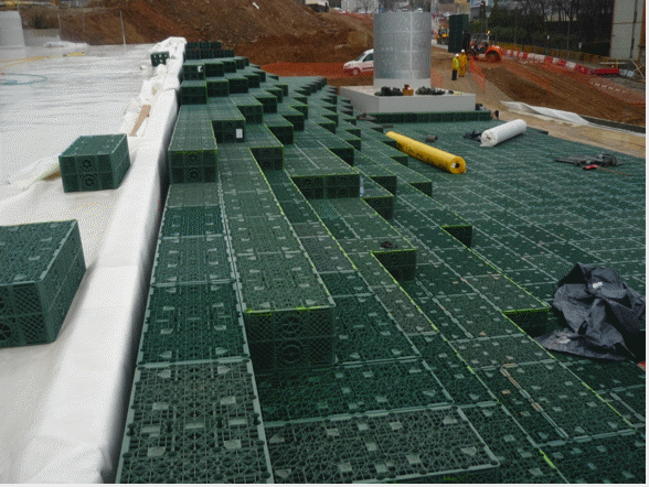
Usually constructed using high-strength geocellular systems, or plastic modules with a high void rate able to support road traffic. If they are covered with vegetation, it must tolerate flooding.
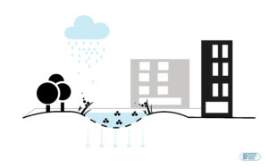
Diagram of Rainwater retention and infiltration elements located in community spaces
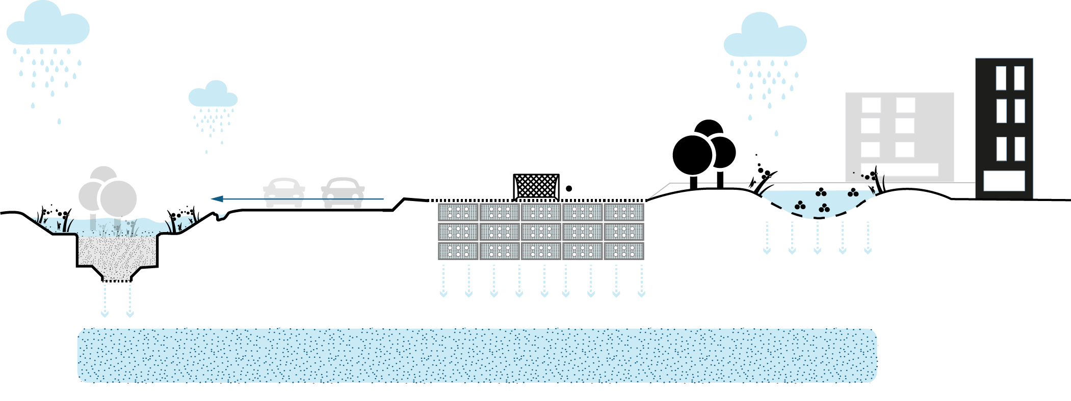
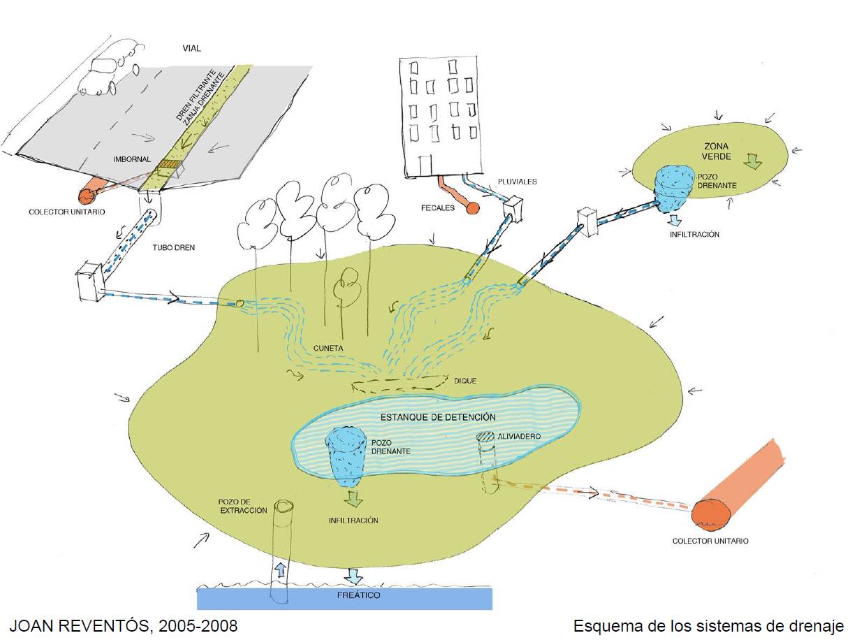
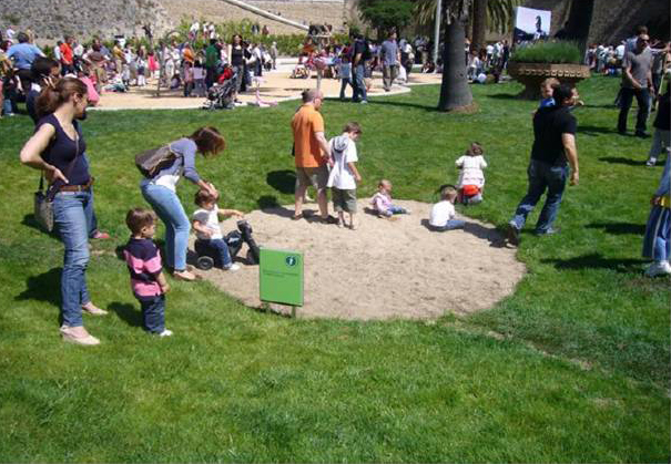
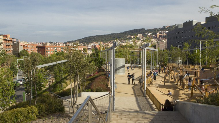
Retention Ponds in Parque Joan Revéntos and infiltration deposits in Parque de las Rieras de Horta.
Source: Gestión Urbanística, Ayuntamiento de Barcelona,SOTO FERNÁNDEZ, R. (2016)

District scale intervention

ISSUES AFFECTED
SUITABLE FOR COMBINING WITH OTHER SOLUTIONS
MEASURE ELEMENTS
Indicator
Reduction of energy consumption by infiltration or capture of rainwater (∆CE)
Secondary indicator
% of permeable pavement in the street
Unit
m2 of permeable pavement on calle→ ∆CE
Minimo goal
>60%
Desirable goal
>95%
Measure method / Formula
(I1) ΔCE = [A x B]
A: m3 infiltrated
B: Energy consumption in MWh per m3 treated at the WWTP
(I2) % = [A / B]
A: m2 of permeable pavement
B: total area
PLANNING LEVEL
Urban plans
Reform of community spaces
Special plans (university campuses, hospitals)
AGENTS INVOLVED
Local government technicians
Natural areas or water resources agents
Neighbourhood communities
Associations and cooperatives
Real estate developers
Maintenance companies
Design and planning team
Possible actions promoted by the administration
– Mapping of available free soils with high infiltration capacity
– Provide tools for the calculation of collection and reception volumes
What should we consider for its implementation?
– The presence of underground services, such as fiber optics, electrical and telephone cables, or drainage pipes.
– Maintenance of community areas.
– The permeability of the soil, recommending the performance of relevant geotechnical tests to verify the filtering capacity of the soil.
– It is not recommended in areas with unstable soils or zones with risk of contamination (industry, etc.).
– It is necessary to check that the water table is at least 1.2 m below the base of the system.


